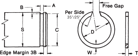
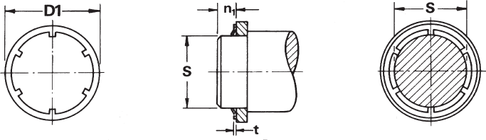
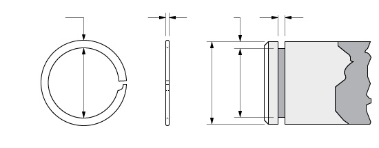
External Snap Ring Groove Dimensions
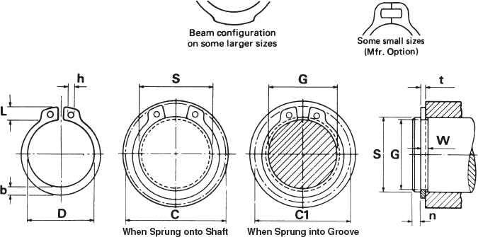
External Retaining Rings External Snap Rings Arcon Ring
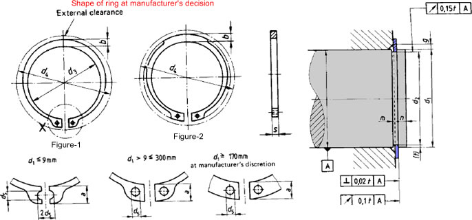
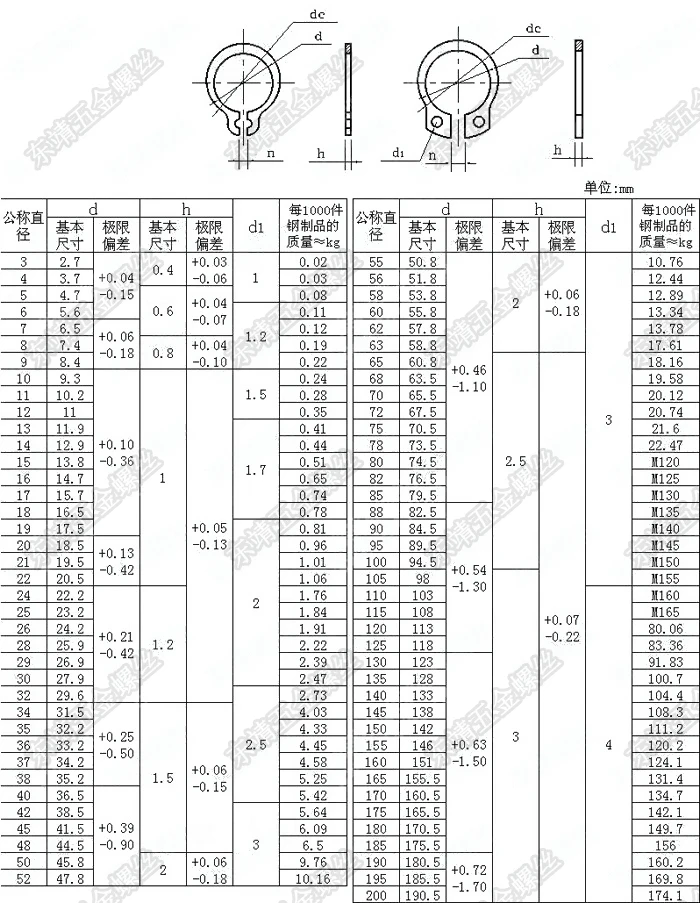
External Circlip Dimensions For Shafts Metric
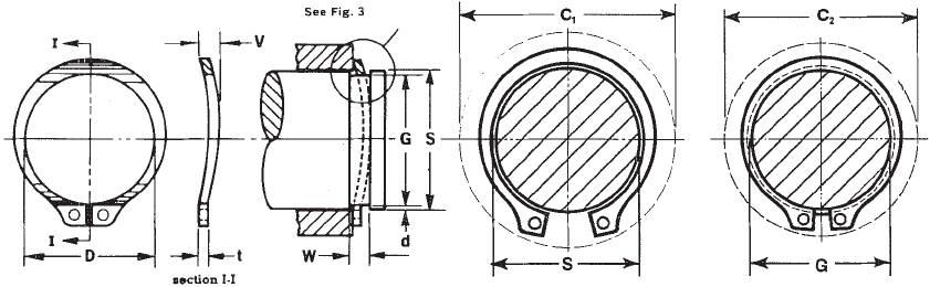
Bowed External Retaining Rings Arcon Ring
Https Www Ametric Com Images Document Retainingrings Pdf
Bearing Snap Rings Arcon Ring
Dimensions Of Snap Ring Grooves And Locating Snap Rings Basic Bearing Knowledge Koyo Bearings Jtekt Corporation

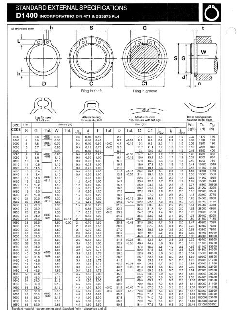
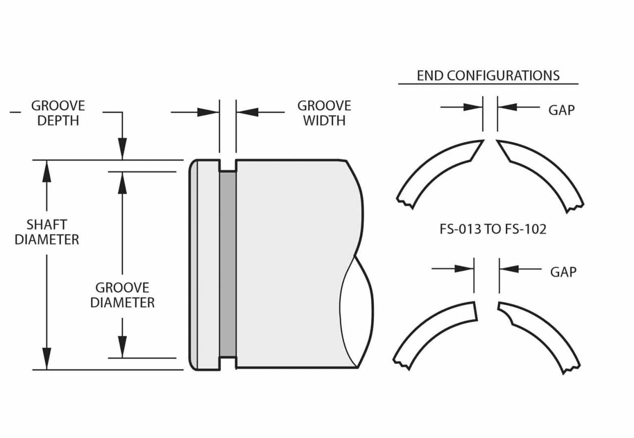
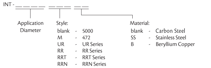
Partnumber application diameter b in groove diameter g in groove width w in groove depth in ring diameter d in ring thickness t in ring.
External snap ring groove dimensions.

Snap Ring An Overview Sciencedirect Topics

The Pic Design Catalog Retaining Rings Gripping External Retaining Rings
Mech 289 External Snap Ring Catalog Cim
Din 471 Snap Rings Metric Xfs Series Tfc
Https Www Repurvis Com Sites Default Files Product Files Rotor Clip Product Catalog Specifications Pdf
External Snap Rings To Din 5417 Springmasters
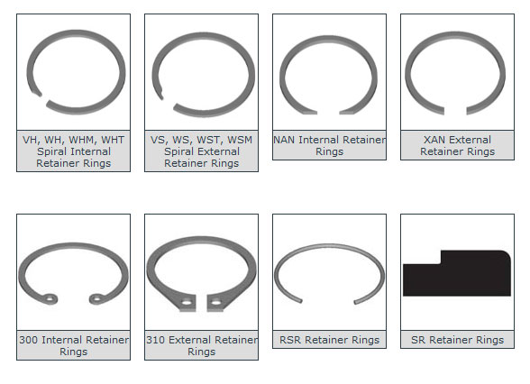
Retaining Rings Types And Applications Engineers Edge
40pcs M22 Din471 C Type Snap Retaining Ring For 22mm External Shaft Circlip Retaining Ring Snap Retaining Ringcirclip Snap Ring Aliexpress
External Push On Retaining Rings Arcon Ring
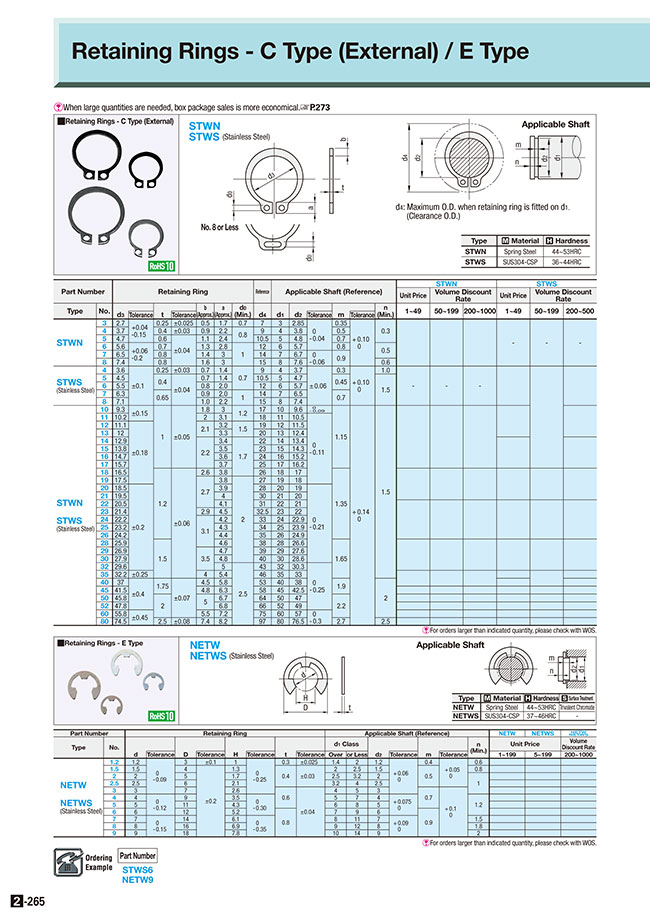
Retaining Rings External C Type Misumi Misumi South East Asia

5100 150 Shaft Retainer Ring 5100 View Shaft Retainer Ring Ew Product Details From Shanghai Eastern Waves Co Ltd On Alibaba Com

Retaining Rings Stainless Steel External Automotive 316 Pieces Nut And Bolt Storage Snap Ring Stainless Steel
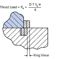
Load Capacity Smalley

Sdfsx 4 Piece Snap Ring Pliers Set Internal External Circlip Pliers Kit Tip Diameter 0 07 Circlip Plier Set Straight Bending P Snap Ring Ring Shapes Pliers

Cysd Bearings In 2020 Skf Roller House Materials

Xiamen Most Sports Goods Co Ltd Fun Sports Bottom Bracket How To Remove

30x42x30 Bearing In 2020 Roller Skf Surface Roughness

Creality Ender 3 Enclosure By Fourdogs Impressora 3d Impressoras Impressao 3d
Https Encrypted Tbn0 Gstatic Com Images Q Tbn 3aand9gcspw8rzwan 5hfol Il3eyov3b2gl4b5asbcncfzjoacyrrxwh Usqp Cau
Retaining Rings Wave Washer Teflon Products O Ring Kits Teflon Tape Custom Molded Plastic Parts Custom Extruded Plastic Shapes
Metal Components Retaining Rings

Stainless Steel Internal Snap Ring Kit 121 Piece Nut And Bolt Storage Steel Snap Ring
Vsm 12 Smalley

1 Or 1 1 4 Retaining Ring Snap Ring 01528 Or 600841 Bmi Karts And Parts
Source : pinterest.com
